

Process and Instrumentation Diagrams (P&IDs) are the backbone of industrial operations. Whether you are working in oil and gas, pharmaceuticals, food processing, power generation, or manufacturing, understanding how to extract process details from a P&ID is an essential skill. At first glance, these diagrams may look complex and overwhelming—full of lines, symbols, bubbles, and codes—but once you know how to read them systematically, they become incredibly informative maps of your entire process system.
TLDR: A P&ID shows how industrial processes function through equipment symbols, piping connections, instruments, and control loops. To extract process details, start with the legend, identify major equipment, trace piping and flow direction, understand instrument symbols, and review control strategies. Pay attention to line types, tag numbers, and safety devices for deeper insight. By following a structured step-by-step approach, you can quickly turn a complex drawing into a clear understanding of how the process operates.
Step 1: Start with the Legend and Title Block
Before diving into the diagram itself, take time to review the legend and title block. These sections contain critical information that defines how the rest of the drawing should be interpreted.
- Legend: Explains symbols for valves, instruments, line types, and equipment.
- Title block: Identifies drawing number, revision, project name, and date.
- Notes section: Often includes process conditions or standards used.
Different companies may follow slightly different standards, even if they generally align with ISO or ISA guidelines. Never assume symbols mean the same thing across all drawings—always confirm with the legend first.
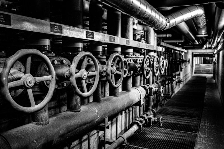
Image not found in postmetaStep 2: Identify the Major Equipment
Once you understand the symbols, start by locating the primary equipment in the process. These elements define the backbone of the system.
Look for:
- Pumps
- Compressors
- Heat exchangers
- Reactors
- Storage tanks
- Columns and separators
Each piece of equipment will have a tag number, such as P-101 (pump), E-205 (heat exchanger), or V-301 (vessel). This tag is your reference point for gathering additional information from:
- Equipment datasheets
- Process flow diagrams (PFDs)
- Equipment lists
- Maintenance systems
At this stage, focus on answering these questions:
- What are the main process units?
- How many major process stages exist?
- Where does the process start and end?
Understanding equipment layout gives you a structural view of the process before diving into detailed instrumentation.
Step 3: Trace the Process Flow
Next, follow the flow direction of the process streams. Piping lines connect all equipment and show how fluids move through the system.
Pay attention to:
- Arrows indicating flow direction
- Line numbers identifying specific process lines
- Line types (solid, dashed, dotted)
- Pipe size and material specs
The line number often encodes valuable details such as:
- Pipe diameter
- Fluid service
- Line class
- Insulation requirements
By tracing each line from one piece of equipment to another, you can reconstruct the physical path of the fluid through the plant.

Step 4: Decode the Instrumentation Bubbles
Instrumentation is where the P&ID becomes truly informative. Instrument symbols (usually circles or bubbles) contain coded letters that describe their function.
For example:
- F = Flow
- P = Pressure
- T = Temperature
- L = Level
Common combinations include:
- FT – Flow Transmitter
- PT – Pressure Transmitter
- TIC – Temperature Indicating Controller
- LIC – Level Indicating Controller
The letters are not random—they follow industry standards. The first letter represents the measured variable, and subsequent letters represent the function (indicating, recording, controlling, etc.).
Also note the line style connected to the instrument:
- Solid line = Process connection
- Dashed line = Electrical signal
- Dotted line = Pneumatic signal
- Double line = Capillary tubing
These line styles tell you how the instrument communicates and operates within the control system.
Step 5: Understand Control Loops
Control loops are the heart of process automation. A loop typically consists of:
- A measuring device (transmitter)
- A controller
- A final control element (usually a control valve)
For example, in a temperature control loop:
- The temperature transmitter measures process temperature.
- The temperature controller compares it to a setpoint.
- The control valve adjusts flow to maintain temperature.
By carefully following instrument tag numbers (such as TIC-101 connected to TV-101), you can map the entire feedback loop.
Ask yourself:
- What variable is being controlled?
- What is manipulating that variable?
- Where is the measurement taken?
This step helps you understand not just how the system is built—but how it behaves.

Step 6: Identify Valves and Their Functions
Valves appear everywhere in a P&ID, and each serves a specific purpose. Understanding valve types is critical for extracting process details.
Common valve types include:
- Gate valves – Isolation
- Ball valves – Quick shutoff
- Check valves – Prevent backflow
- Globe valves – Throttling
- Control valves – Automatic regulation
- Relief valves – Overpressure protection
Each valve symbol visually differs, so comparing it with the legend is essential. Additionally, valve tag numbers provide a reference for maintenance or operational procedures.
Step 7: Look for Safety and Protection Systems
A P&ID also shows critical safety elements. These are essential for hazard analysis and compliance.
Key safety components include:
- Pressure relief valves (PSVs)
- Rupture discs
- Emergency shutdown valves (ESD)
- Flare connections
- Interlocks
Some diagrams also show safety instrumented functions (SIFs). These are typically highlighted or referenced separately and may be connected to safety PLC systems.
Whenever analyzing a process for risk, always identify:
- Overpressure protection points
- Isolation capabilities
- Emergency drain paths
- Bypass lines
This information is invaluable for HAZOP studies and troubleshooting scenarios.
Step 8: Cross-Reference with Other Documents
A P&ID does not exist in isolation. To get full process details, cross-reference it with:
- PFDs (Process Flow Diagrams) for overall mass and energy balance
- Equipment datasheets for ratings and dimensions
- Instrument index for full tag details
- Control philosophy documents for automation strategy
- Line list for piping specifics
The PFD shows the “big picture,” while the P&ID provides detailed implementation. Jumping between these documents completes your understanding.
Step 9: Build a Mental (or Physical) Narrative
To truly extract process details, practice explaining the process in plain language:
“Fluid enters through pump P-101, flows through heat exchanger E-201 where it is heated by steam, then moves to reactor R-301 where temperature is controlled by TIC-301, and finally exits to storage tank V-401.”
If you can narrate the process, you understand it. If you get stuck, revisit the relevant area of the P&ID.
Common Mistakes to Avoid
- Ignoring revision numbers
- Assuming symbols without checking the legend
- Confusing electrical and pneumatic signals
- Overlooking bypass lines
- Forgetting that P&IDs are not to scale
Even experienced engineers occasionally misread small details. Slow, methodical analysis is more effective than rushing.
Why This Skill Matters
Being able to extract process details from a P&ID allows you to:
- Troubleshoot operational issues
- Support commissioning activities
- Participate effectively in design reviews
- Perform safety assessments
- Communicate clearly with multidisciplinary teams
In many industries, this skill distinguishes a junior engineer from a seasoned professional.
Final Thoughts
A P&ID may look intimidating at first, but it is essentially a structured language. Once you understand the grammar—symbols, line types, tagging conventions, and control logic—you can read it like a story.
The key is to approach it step by step: start with the legend, identify equipment, trace flow paths, decode instrumentation, analyze control loops, review safety features, and cross-reference supporting documents. With practice, extracting process details becomes not just manageable, but genuinely fascinating.
A well-read P&ID doesn’t just show you piping and valves—it reveals how the entire process thinks, reacts, and protects itself.